Як правильно зібрати ПК самому

Ми незалежно перевіряємо товари та технології, які рекомендуємо.

Список комплектуючих, інструментів та витратних матеріалів
Процес збирання ПК починається з вибору комплектуючих, які повинні бути сумісні за роз'ємами, технологіями, характеристиками. У масштабі цієї статті докладно зупинятися на цих моментах немає сенсу, оскільки ми маємо окремі гайди, посилання на які будуть вказані. Ми ж керуватимемося тим, що всі компоненти збірки вже на руках і потрібно правильно укомплектувати все в системному блоці. Варто зазначити, що список комплектуючих може трохи відрізнятися в залежності від рівня комп'ютера. Розглянемо два шаблонні варіанти, які є актуальними для переважної кількості збірок.
| Домашній / офісний ПК | Ігровий ПК |
|---|---|
| Материнська плата | Материнська плата |
| Процесор з інтегрованою графікою та боксовим кулером | Процесор |
| Оперативна пам'ять | Оперативна пам'ять |
| Накопичувач M.2 / SSD / HDD | Накопичувач M.2 / SSD / HDD |
| Блок живлення | Блок живлення |
| Корпус | Корпус |
| Вентилятори | Вентилятори |
| Вежевий кулер або СРО | |
| Дискретна відеокарта |
Тепер давайте визначимося, які інструменти та витратні матеріали можуть знадобитися для підключення та фіксації деталей:
- Невелика хрестова викрутка з магнітним наконечником (оптимально PH1 близько 20 см завдовжки)
- Термопаста (популярною та універсальною є Arctic Cool MX4)
- Поліетиленова рукавичка
- Холодний розум, відкриті очі і руки, що не тремтять.
Порядок встановлення може трохи відрізнятися в залежності від можливостей корпусу, комплектуючих, що використовуються, і звичок майстра. Ми пропонуємо найбільш популярний алгоритм дій, який підійде для збирання більшості ПК. Отже, дістаємо материнську плату, кладемо на рівну чисту поверхню. Рекомендується підкласти м'який шар, наприклад, спінений поліетилен.
Особливості встановлення процесорів AMD та Intel
Насамперед необхідно встановити процесор. Для цього на материнській платі передбачено спеціальний роз'єм, який ще називають Сокет. Різні покоління чипів від AMD та Intel мають своє компонування. Якщо ви ще не зібрали ядро, рекомендуємо ознайомитися з особливостями вибору материнської плати і процесора, щоб не помилитися і забезпечити повну сумісність і максимальну ефективність комп'ютера.
Для AMD та Intel принцип підключення однаковий, різниця лише у будові компонентів. У перших контактні ніжки розташовані безпосередньо на процесорі, а пази для них знаходяться на материнці. У Intel все з точністю навпаки. Головним правилом є дбайливе поводження. Необхідно виключити будь-який тиск та зусилля, щоб не пошкодити контакти. Встановлення має здійснюватися невимушено.
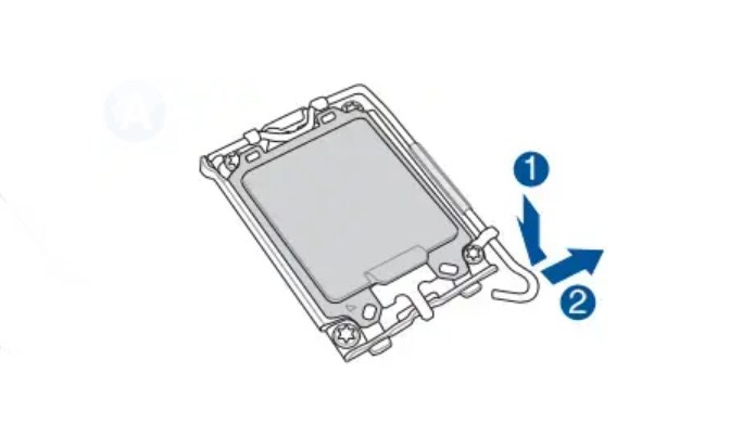
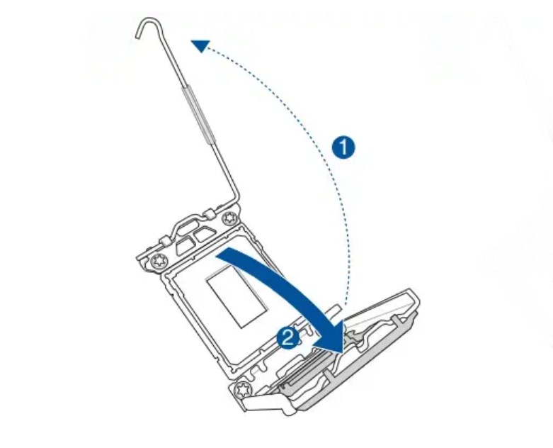
Реалізувати це все на практиці дуже просто. Для початку необхідно розблокувати роз'єм на материнській платі.
Щоб правильно визначити, якою стороною вставляти ЦП, виробники передбачили спеціальні ключі. Вони представлені заглибленнями в корпусі та маркерами-трикутниками.
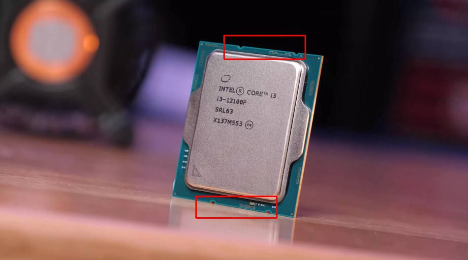
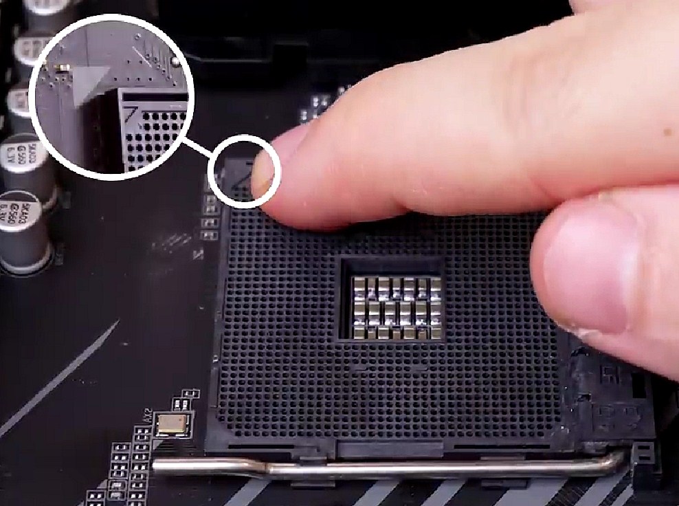
Достатньо поєднати їх і плавно опустити чип на своє місце. Після чого роз'єм блокується у зворотному порядку.
Які проблеми можуть виникнути на цьому етапі? Фактично лише одна — процесор не встановлюється у роз'єм. Причиною може бути неправильно підібраний сокет або погнуті контакти (актуально для AMD). У першому випадку на вас чекає заміна комплектуючих, у другому потрібен візуальний огляд під різними кутами та акуратне вирівнювання ніжок.


Як правильно встановити оперативну пам'ять
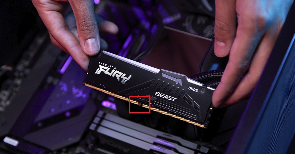
Встановлення ОЗП не повинне завдати клопоту. Відмінність між поколіннями (DDR3 / DDR4 / DDR5) тільки в ключі, який і допоможе правильно розташувати її в роз'ємі.
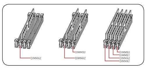
Але для початку необхідно визначитися, які слоти використовувати для підвищення ефективності збирання. Їх може бути 2 або 4 (стандарт для домашніх та ігрових збірок), якщо звичайно не йдеться про спеціалізовані серверні рішення.
В залежності від кількості модулів пам'яті та слотів на материнській платі схема правильного підключення виглядає таким чином.
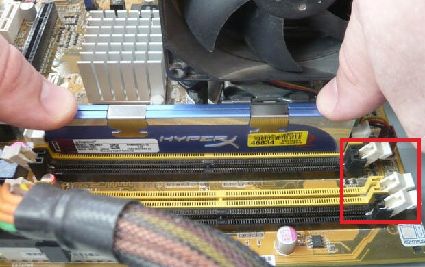
Для початку необхідно відкрити замки з боків на материнській платі. Далі повертаємо модуль пам'яті так, щоб ключі збіглися, вставляємо і з невеликим зусиллям натискаємо з обох боків, поки замки автоматично не замикаються.
Якщо у фіналі комп'ютер запуститься з чорним екраном, то можливо, ви неправильно підібрали характеристики ОЗП, тому вона не сумісна з іншими комплектуючими. Рекомендуємо ознайомитися з інстркцією з вибору оперативної пам'яті.


Підключення M.2 накопичувача
Варто відразу зазначити, що наявність накопичувача даних формату M.2 не є обов'язковою умовою, а деякі користувачі все ще дивляться у бік бюджетніших SSD SATA 2.5” або HDD. Але треба розуміти, що M.2 у всьому перевершує своїх попередників, а різниця в ціні незначна, тому краще відразу віддати перевагу цьому накопичувачу. Докладніше про вибір SSD накопичувача можна дізнатися у відповідній статті, а ми переходимо безпосередньо до встановлення.
Для M.2 у материнській платі передбачений спеціальний слот, а може бути й кілька. Розташовується він між процесором і PCIe під відеокарту (додаткові зазвичай знаходяться в нижній частині плати) і виглядає так.
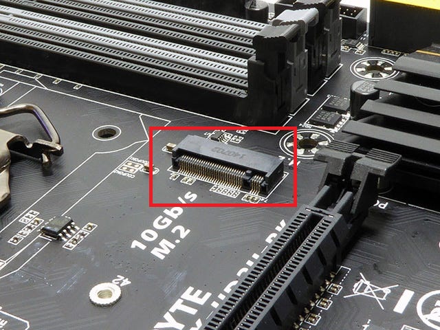
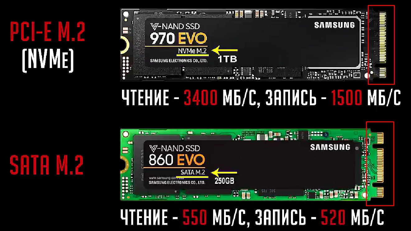
Ви можете вибрати один із двох типів SSD M.2 – з інтерфейсом підключення PCIe або SATA.
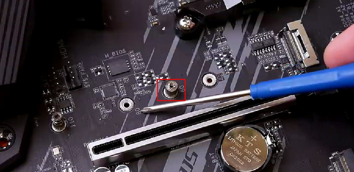
Як і для інших комплектуючих, тут передбачені ключі, які допоможуть правильно розмістити модулі в роз'ємах. Якщо комплектація материнської плати передбачає радіатор охолодження для M.2, то необхідно попередньо його зняти. Тепер вкручуємо підставку для фіксації в отвір, що відповідає розміру SSD. Стандартом є 80 мм.
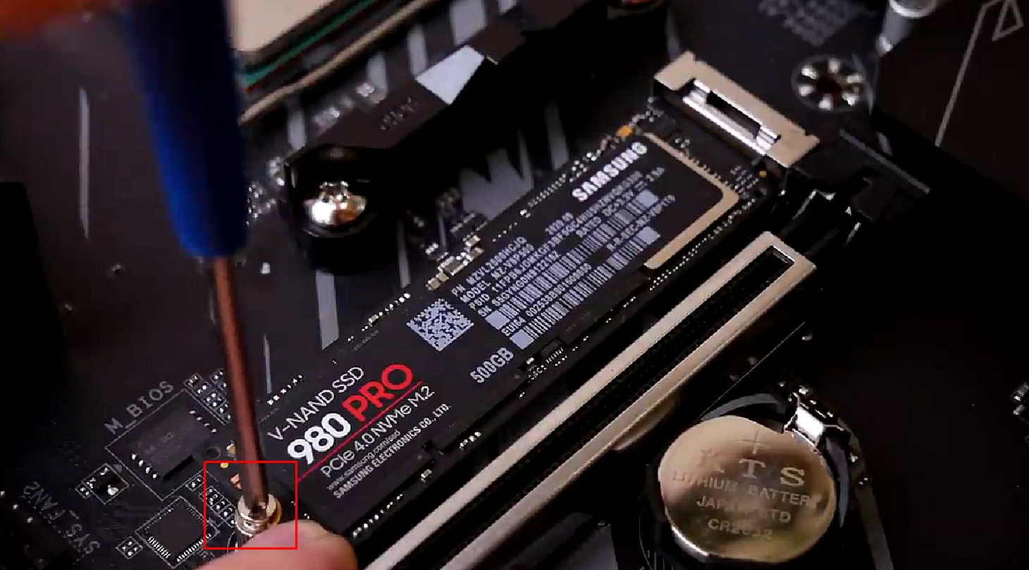
Далі вставляємо накопичувач у роз'єм, щоб збіглися ключі (робити це потрібно під кутом близько 30º відносно плати), притискаємо. Якщо був радіатор, знімаємо з нього захисну плівку і ставимо назад, прикручуємо його і SSD.


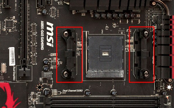
Монтаж системи охолодження процесора
Наразі саме час підготувати площадку для встановлення охолодження ЦП. Якщо плануєте використання боксового кулера, то монтажні планки/отвори під нього зазвичай вже присутні на материнській платі. Варто зазначити, що червона команда (AMD) подбала про максимальну зручність для користувача в цьому питанні.
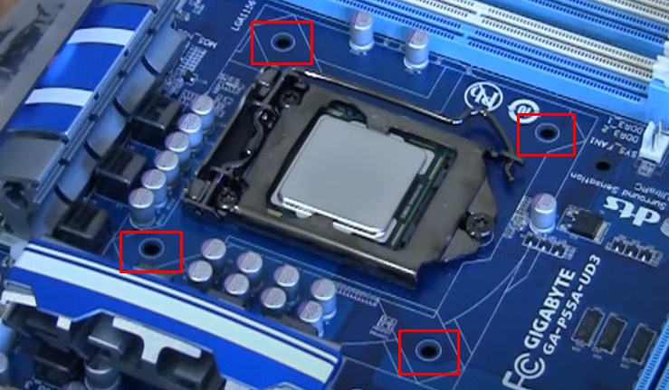
Тоді як сині (Intel) змусять трохи попітніти.
Штатні системи охолодження досить компактні, тому можна провести їхній повний монтаж вже на цьому етапі. Надалі вони не заважатимуть.
Варіантів встановлення прогресивніших систем охолодження багато в залежності від сокету та типу (вежа або СРО). Насамперед, потрібно керуватися інструкцією, яку пропонує виробник кулера. Наприклад, ось послідовність встановлення популярної вежі Deepcool GAMMAXX 400K (https://www.deepcool.com/download/pdf/GAMMAXX400Series.pdf). Важливо правильно підібрати систему, що охолоджує. Зверніть увагу на комплект постачання, щоб він включав кріплення під різні сокети. Визначитись з вибором допоможе відповідний гайд.
Потрібно пам'ятати, що не всі корпуси мають вікно для бекплейта (металева підсилювальна пластина, яка кріпиться зі зворотного боку плати), тому його монтаж необхідно виконати до встановлення материнської плати. Не затискайте деталі дуже сильно, щоб не зашкодити друкованій платі.
Також не забувайте про важливість нанесення термопасти. Це забезпечить покращене відведення тепла та нормальні робочі температури. Видавіть невелику кількість, одягніть поліетиленову рукавичку і рівномірно розподіліть пальцем склад по поверхні ЦП. При встановленні кулера паста заповнить усі пори, а надлишки вичавляться назовні. У деяких випадках термопаста вже нанесена виробником на підошву кулера і залишається лише провести його монтаж, підключити до плати.


Встановлення материнської плати у корпус
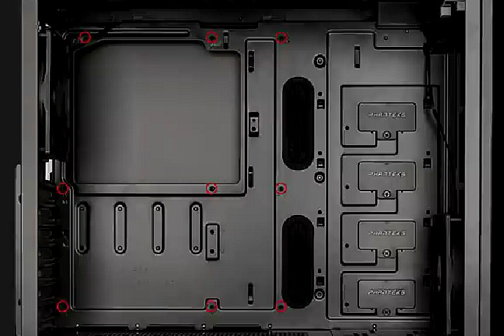
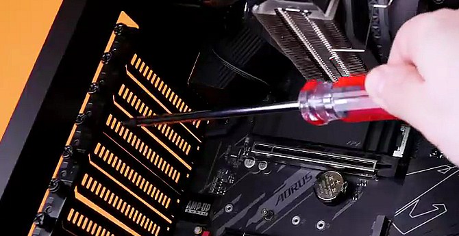
Наступним кроком необхідно встановити зібрану материнську плату у корпус. Спочатку встановіть платформи для фіксації, щоб вони відповідали отворам на платі.
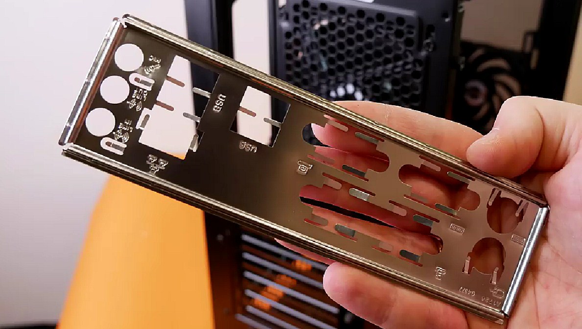
Далі встановіть металеву заглушку у задню стінку корпусу. У середньому та топовому сегменті вона може бути вмонтована у плату.
Тепер залишається вставити материнку і вкрутити всі фіксуючі гвинти викруткою.


Підключення SSD та HDD
Якщо ви все ж таки відмовилися від M.2 або вирішили використовувати додатковий накопичувач, то необхідно визначитися з місцем під SSD 2.5” або HDD 3.5”. Для цього доведеться вивчити специфікацію корпусу, тому що певного шаблону немає, і внутрішнє компонування може бути найрізноманітнішим. Для фіксації можуть застосовуватися швидкознімні кріплення або стандартні гвинти.
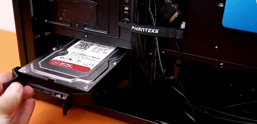
Для жорстких дисків у сучасних кейсах передбачено окремий кошик у нижній частині. Він може бути як знімним, так і стаціонарним. Необхідно лише вставити та закріпити гвинтами з боків.
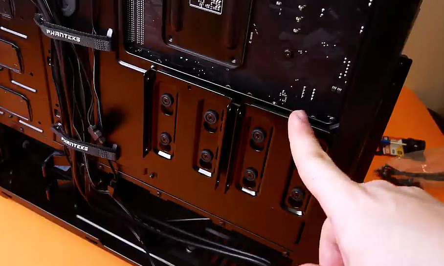
Місця під SSD 2.5” можуть виглядати таким чином.
Загальні рекомендації: для роботи HDD та SSD буде потрібне підключення кабелів живлення та передачі даних, тому необхідно розмістити їх у корпусі так, щоб зручно було робити розведення дротів в подальшому.


Монтаж блоку живлення та розведення кабелів
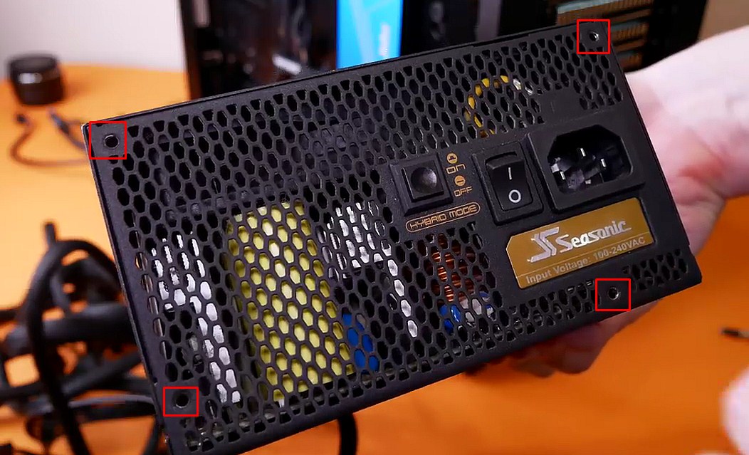
Посадкове місце для блока живлення стандартне і передбачає кріплення на 4 гвинти.
Якщо у вас фіксовані кабелі, джерело живлення можна сміливо монтувати. Більшість сучасних корпусів орієнтовані на нижнє розташування БЖ, але існують модифікації і з верхнім.
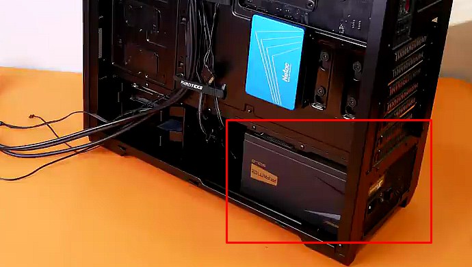
Для моделей із модульним підключенням можна зробити аналогічно за умови великого корпусу (Full або Midi Tower), де достатньо місця для маневрів. Якщо збірка компактна (Mini Tower), спочатку доведеться розвести всі кабелі, підключити їх до блока живлення, а потім закріпити його в корпусі. Вентилятор повинен розташовуватись знизу для безперешкодного доступу повітря.
Тепер важливо зрозуміти, що й куди вести. Виробники зробили процес максимально простим, передбачивши різні форми роз'ємів та замки. Переплутати щось чи засунути не тією стороною неможливо.
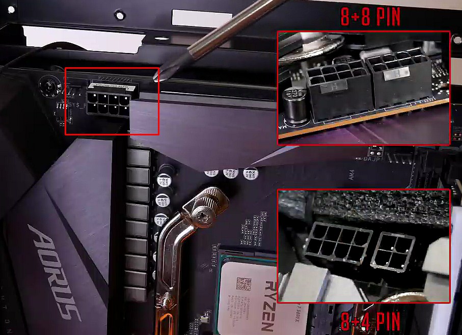
Роз'єм для живлення процесора знаходиться у верхній частині материнської плати. Його конфігурація може відрізнятися, оскільки для роботи ЦП різних рівнів потрібна певна потужність. На малюнку нижче можна побачити популярні варіанти розпінування, отвір вгорі для підведення кабелю та замки для правильної орієнтації та фіксації.
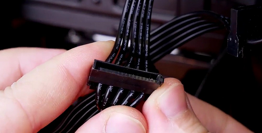
Відповідні виходи на блоці живлення виглядають таким чином.
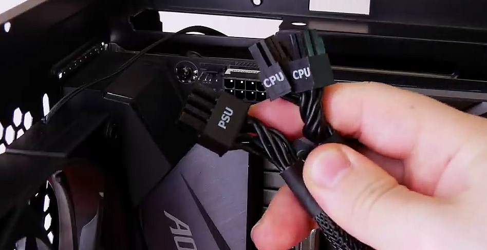
Підключення здійснюється до клацання, яке сповістить про закриття замка.
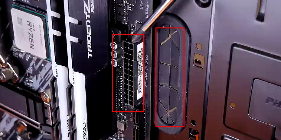
Наступним кроком підключаємо живлення материнської плати. Для цього використовується роз'єм 24 PIN, показаний нижче разом з отвором в корпусі для підведення кабелю.
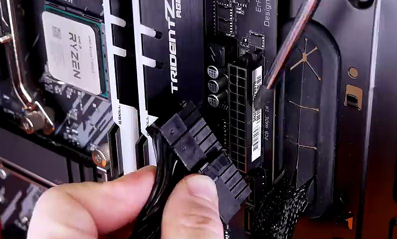
Знаходимо відповідний модуль на блоці живлення, протягуємо, натискаємо до клацання.
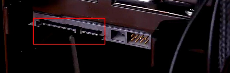
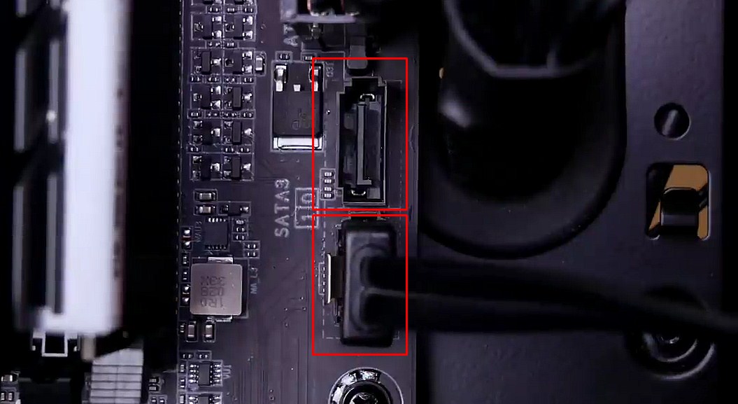
Тепер настав час заживити накопичувачі HDD / SSD, якщо вони є. Роз'єм на БЖ виглядає наступним чином, називається SATA (зазвичай їх мінімум 4).
Він має своєрідний виріз із одного краю, який утворює кут. Аналогічна реалізація передбачена на дисках, тому переплутати не вдасться.
Довгий роз'єм для підключення живлення від БЖ, а короткий для кабелю SATA передачі даних. Останній не відноситься до блока живлення та синхронізується з материнською платою.
Не забуваємо витягнути залишки дротів назад, щоб вони не плуталися і не псували естетику збірки.
Тепер усі пристрої забезпечені живленням. Якщо використовувався модульний БЖ, настав час підключити до нього всі кабелі і встановити його в корпус.


Встановлення корпусних вентиляторів
Додаткові вентилятори не є обов'язковою умовою, але бажано мати хоча б парочку. Вони призначені для циркуляції повітря всередині системного блока та ефективного охолодження. Наявність посадкових місць та їх кількість у корпусі різна залежно від моделі, але загальний принцип правильного встановлення показано на малюнку нижче.
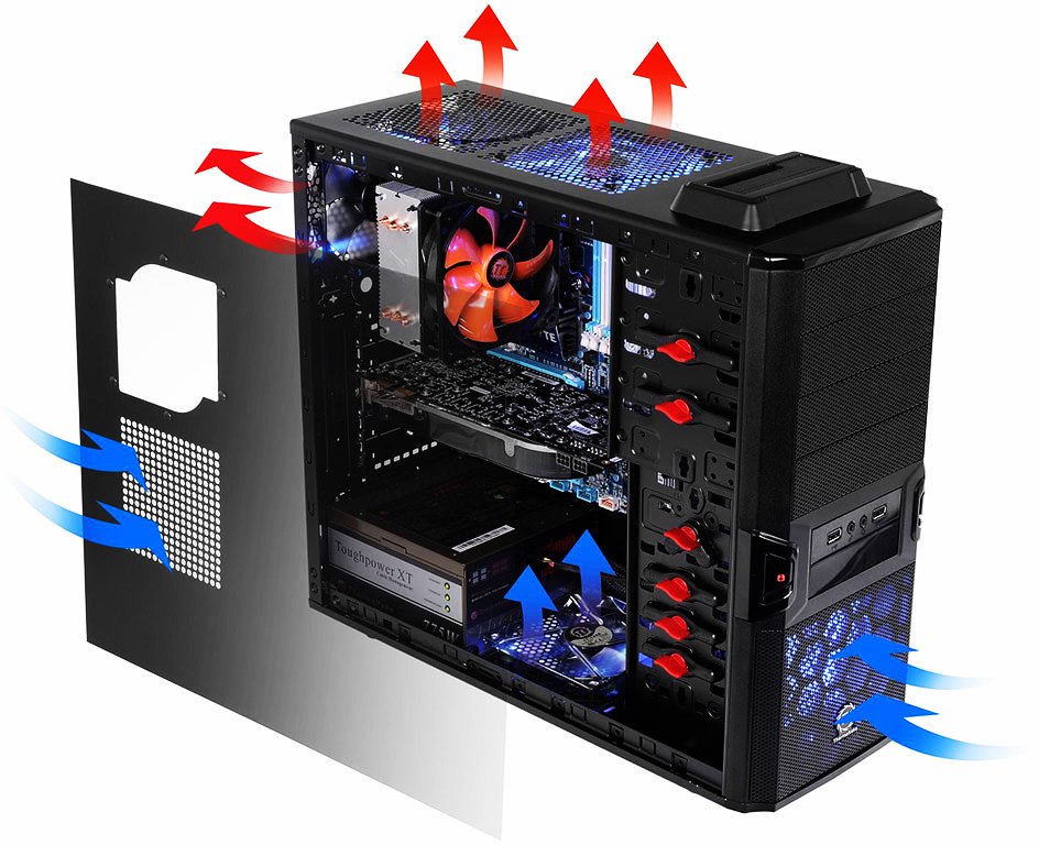
Для забору повітря призначена передня, нижнє та бокова панелі, а для видування – верхня та задня. Навіть у компактних кейсах за знімною фронтальною панеллю можуть спокійно розташуватися дві вертушки на 120 / 140 мм. Достатньо визначити напрямок потоку та закріпити вентилятори гвинтами.
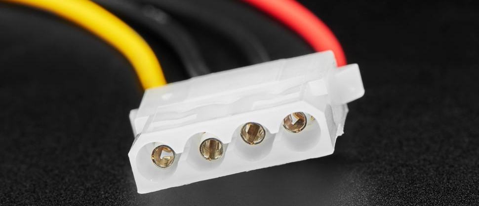
Далі буде потрібно підключити обладнання. Існує 3 варіанти роз'ємів 3 PIN, 4 PIN та Molex. Останній є найбільш примітивним і не підтримує жодних регулювань, струм подається напряму від блока живлення через однойменний контакт.
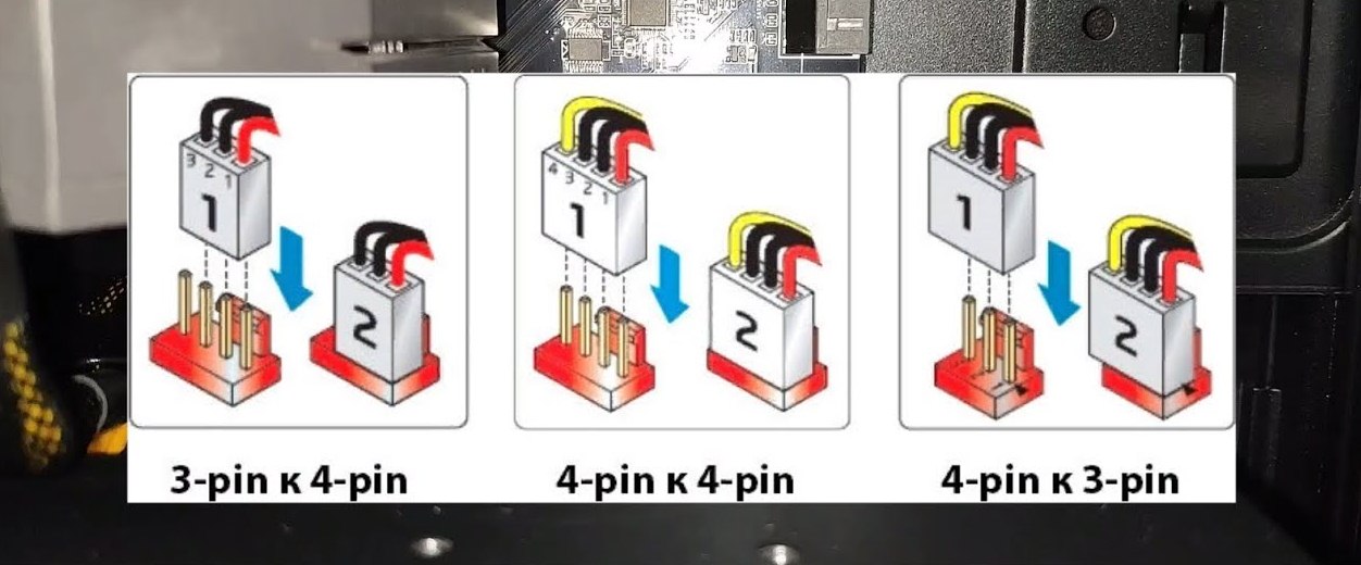
Різниця між 4 PIN та 3 PIN – в наявності додаткового керуючого каналу, який дає змогу автоматично регулювати оберти. На практиці обидва роз'єми материнської плати для корпусних вентиляторів підписані як SYS_FAN і взаємно сумісні, а схема підключення така.
Якщо у вас ігровий комп'ютер з топовим процесором, то практичніше використовувати систему рідинного охолодження, монтаж якої краще проводити до встановлення материнської плати в корпус.


Підключення панелі управління корпуса
Типовий комплект роз'ємів панелі управління виглядає так.
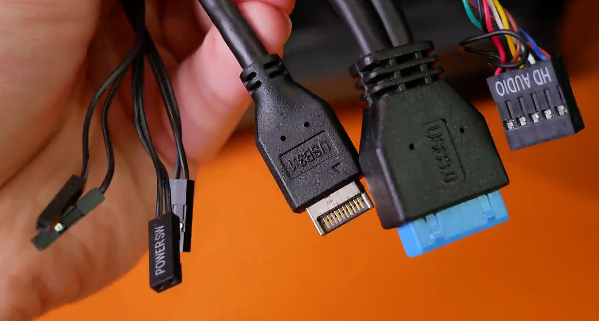
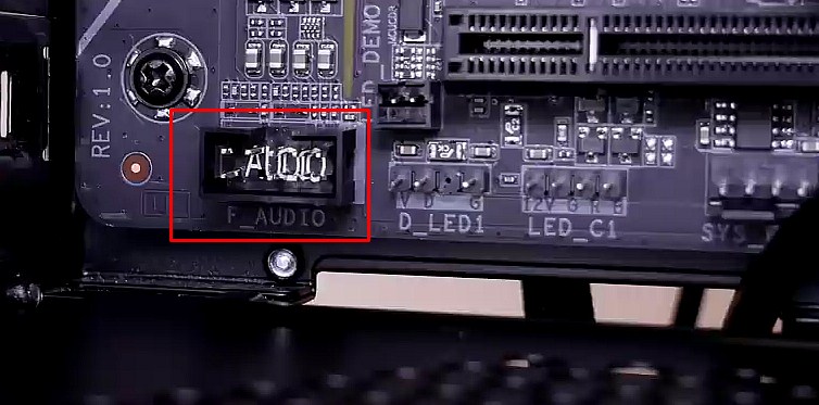
Якщо розглядати справа наліво, то першим йде аудіокабель, для якого на материнській платі передбачене власне місце.
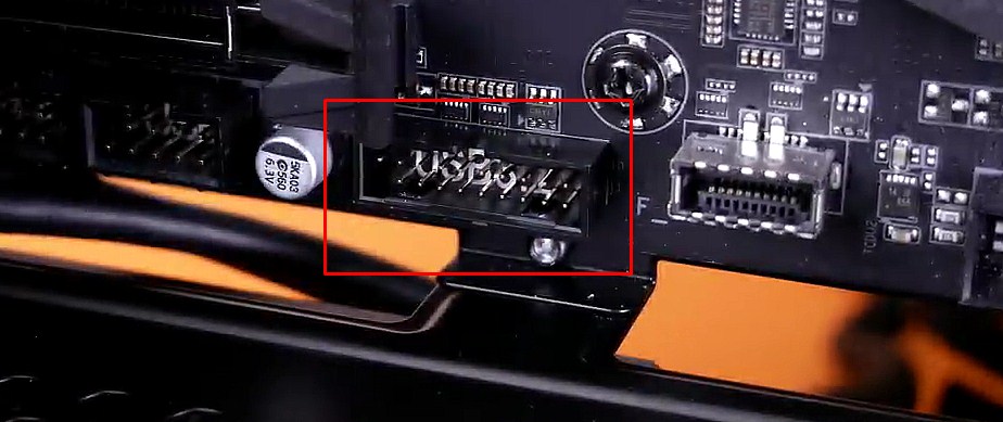
Другим йде USB 3.0, колодка для якого має такій вигляд.
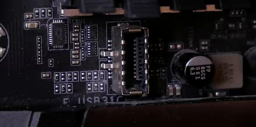
Далі бачимо USB-C, а встановлювати його потрібно в такий роз'єм.
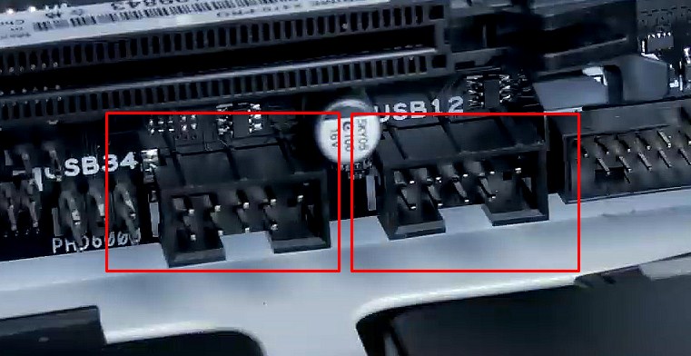
Панель управління майже всіх корпусів стандартно оснащена ще застарілим USB 2.0, який підключається у відповідну колодку.
Тепер настав час розібратися з останніми кабелями, які бентежать багатьох новачків. Йдеться про підключення кнопок та індикаторів.
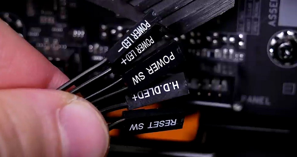
Насправді все дуже просто, а інструкція з розпінування для кожної материнської плати передбачена виробником. Порядок підключення не має жодного значення, колодка підписана як F_Panel, а схема така.
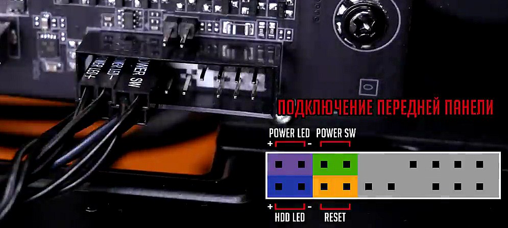
Зверніть увагу, що роз'єми Power SW і Reset не мають полярності, тому можуть вставлятися довільно. Що стосується індикаторів Power LED та HDD LED, то необхідно правильно розмістити «плюс» та «мінус».


Встановлення дискретної відеокарти
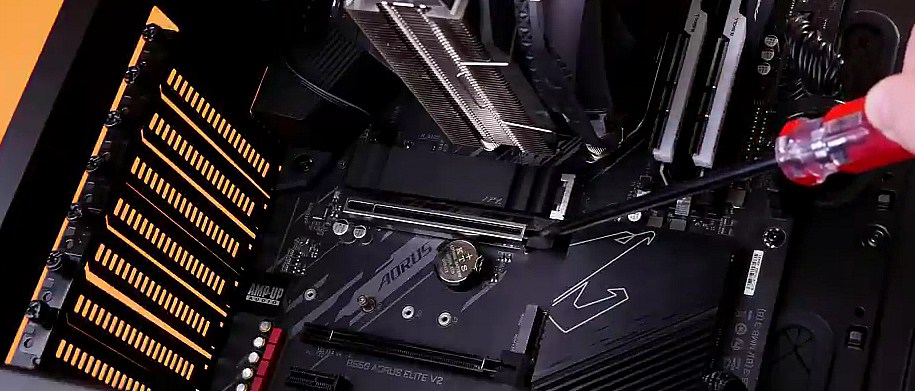
Дискретна відеокарта встановлюється в роз'єм PCIe x16. Варто відзначити, що їх може бути кілька, тому потрібно вибирати верхній. Він знаходиться під процесором і зазвичай підтримує сучасні стандарти та технології, гарантуючи високу продуктивність обладнання.
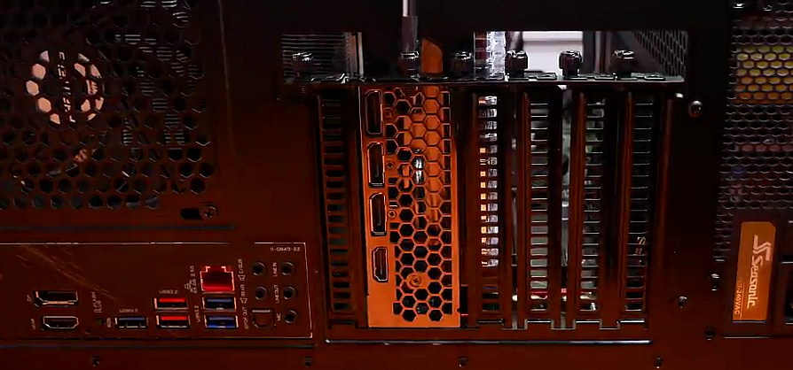
Для початку необхідно прибрати зайві заглушки на задній стінці. Кількість залежить від обраної відеокарти, виробники вказують у специфікаціях кількість слотів, що займаються.
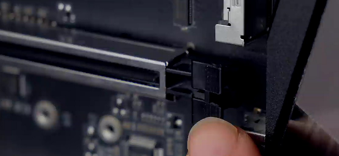
Наступним кроком відкриваємо замок у правій частині роз'єма.
Тепер беремо відеокарту, вставляємо в слот рівно без будь-яких нахилів і акуратно притискаємо, поки не почуємо клацання закритого замка. Фіксуємо пристрій за допомогою гвинтів.
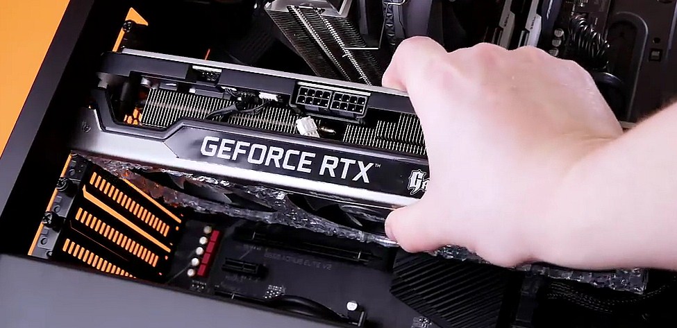
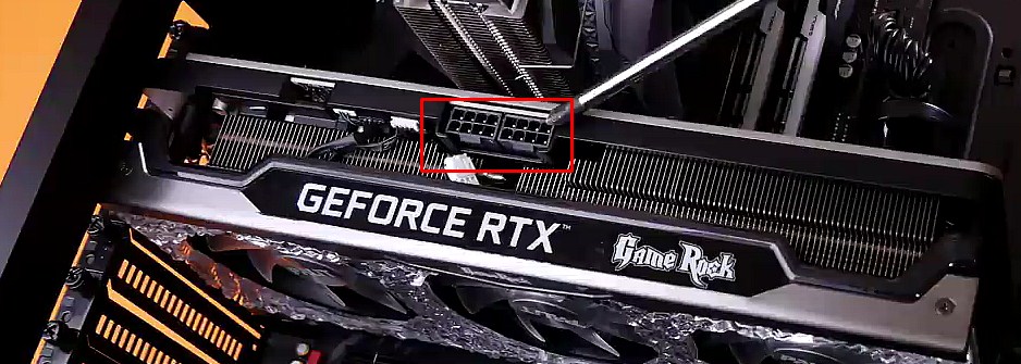
Необхідно знайти відповідні кабелі на блоці живлення та підключити їх для нормального енергопостачання.
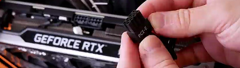
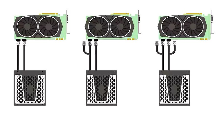
Важливо знати, що для потужних відеоадаптерів може знадобитися підключення відразу кількох фаз. Щоб унеможливити перегрівання і перевантаження БЖ, рекомендується задіяти не суміщені лінії, а окремі, як показано на схемі.
Якщо ви використовуєте вбудовану графіку і тільки плануєте придбання дискретної відеокарти, то рекомендуємо ознайомитися з практичною інструкцією щодо вибору оптимального варіанту.


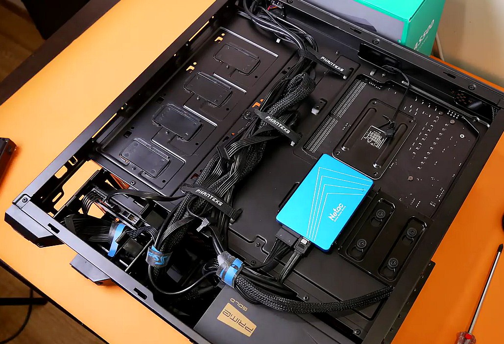
Кабель-менеджмент
Далеко не всіх турбує внутрішня краса системного блоку, але за наявності оглядового вікна та в потужних ПК кабель-менеджмент є ознакою гарного тону. Більше того, грамотне укладання дротів сприяє ефективному охолодженню всіх компонентів комп'ютера. Кожен майстер бачить цей процес по-своєму, а багато моментів залежить від конструкції корпусу. При наявності окремої ніші для прихованого протягування кабелів результат може виглядати наступним чином.
Загалом зручність збірки багато в чому залежить від правильно підібраного корпусу. Не помилитися з вибором допоможе відповідна стаття.
Висновки
Як бачите, зібрати ПК досить просто, але лише за умови правильно підібраних комплектуючих. Порядок встановлення компонентів також має значення, якщо не бажаєте по кілька разів знімати та встановлювати їх. У статті не було враховано деякі моменти, що стосуються професійних ігрових збірок, де часто використовується система рідинного охолодження, стилізація підсвічування та оптимізація внутрішнього простору.


Статті, огляди, корисні поради
Усі матеріали